Cost Breakdown: Renting vs. Buying a Small Road Roller for Construction Projects
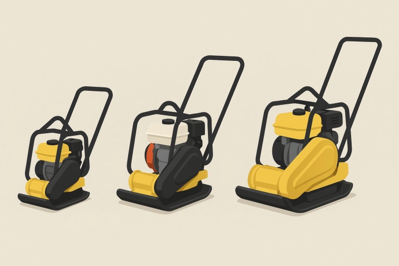
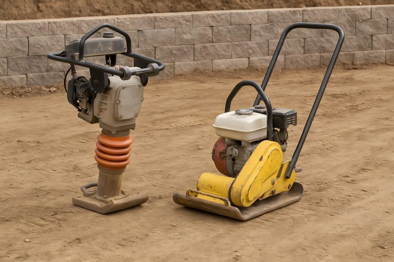
Choosing whether to rent or buy a small road roller can swing your job costs by thousands over a season. This guide breaks down every major cost component—purchase price, rental rates, delivery, fuel, maintenance, insurance, depreciation, and financing—and then walks you through practical break-even examples for two common categories: Walk-behind / pedestrian double-drum rollers (≈24–26 in drums) Compact ride-on tandem rollers (≈1–3 metric tons; ~36–51 in drums) You’ll leave with a decision framework, formulas you can reuse, and “rule-of-thumb” thresholds that help you decide fast. What counts as a “small” road roller? Walk-behind / pedestrian rollers: Typically 24–26 in double drums; widely used for patches, driveways, paths, and tight work zones. Represented by many brands/models; example prices for double-drum pedestrian units in India list around ₹110,000–₹500,000 (≈$1,300–$6,000+) depending on spec and brand. Compact ride-on tandem rollers (≈1–3 ton): Common on parking lots, lanes, shoulders; e.g., Cat CB4.0 (3–5 t, 51 in drums) and Sakai SW354 (≈3 t, 47 in drums). Why this matters: rental rates, purchase prices, fuel burn, and delivery haulage all scale sharply with size. What does renting really cost? Your invoice often includes more than the “headline” daily rate: Base rental rate Typical published rates (size, market, and demand vary): Walk-behind 26″ double-drum: ~$188/day, ~$690/week, ~$1,638/month. Small ride-on 36″–48″: $125–$350/day published examples; weekly ~$1,200; four-week ~$3,100 for a 3–5 ton ride-on. Regional shop examples for 3,000–6,000 lb rollers: $225–$575/day with weekly/monthly discounts. Delivery & pickup (haulage) Local outfits commonly charge a minimum plus per-mile beyond a radius—e.g., $60 each way within 10 miles, then ~$2.50/mile. Expect higher for heavier gear or metro congestion. Damage waiver / rental protection Many dealers add a Loss/Damage Waiver (often 10–20% of the rental rate; one dealer posts 14%). This is not insurance and often excludes negligence/theft caps. Fuel You pay for fuel. (Day/week/month definitions also matter: a “day” is typically one 8-hour shift.) Summary: For a short job, delivery and waiver can add 20–50% to the base day rate. For multi-week jobs, those extras dilute per day. What does buying really cost? Up-front price (CAPEX) Pedestrian double-drum: New units commonly in the low thousands USD range (brand/spec/market dependent). Compact ride-on (≈3 ton): Example listing shows a 3-ton full-hydraulic dual-drum around $32,000; other new 1–3 t options vary widely by brand and region. Ownership costs you’ll carry Depreciation & resale: Expect to recover part of your CAPEX at resale; the spread (purchase minus resale) is your real depreciation cost. Financing (cost of capital): Interest or opportunity cost if you pay cash. Insurance, taxes, registration: Usually a small annual percentage of asset value. Storage & security: Yard space, theft risk mitigation. Maintenance & repairs: Oil/filter services, hydraulics, vibratory system, bearings, water/spray systems, wear parts. Typical service intervals: ~250–500 hours between services, depending on machine class. Fuel: Small rollers vary; indicative reference points: Cat pneumatic rollers list ~1.45–1.8 gal/hr in telematics-based summaries (model dependent). Some small diesel units cite ~1–2 gal/hr; micro/pedestrian diesels can be far lower (e.g., a small Lombardini-powered unit claimed ~1.35 L/hr). Treat these as ballpark, not promises, and check your model’s spec sheet. Tip: Your dealer’s cost-per-hour templates (or EquipmentWatch Blue Book methodology) split ownership (fixed, per month or year) and operating (per hour), which is the most reliable way to compare. Tax treatment (U.S.) Many buyers can elect Section 179 / bonus depreciation (limits change; verify the current year) instead of straight-line MACRS. For authoritative guidance, use IRS Publication 946 and your CPA; online summaries often lag law changes or conflict. Build a comparable cost model Use a 3-bucket structure: Fixed ownership (per year) = Depreciation (Purchase − Expected Resale)/Years + Insurance/Taxes + Financing cost. Variable ownership (per day) = (Fuel/hr + Maintenance/hr) × Hours/day. Rental (per day) = Base day rate + Damage waiver + (Delivery ÷ Job days) + Fuel. You’re finding D (days/year) where: Fixed_own/year ÷ D + Variable_own/day = Rental/day Solve for D to get your break-even utilization. Worked example A — Compact ride-on (≈3-ton) tandem Assumptions (illustrative, adjust to your reality): Purchase price: $32,000 (3-ton class example). Resale after 3 years: $16,000 (50%—varies by brand/market). Depreciation: ($32,000 − $16,000) ÷ 3 = $5,333/year. Insurance/taxes/storage: $1,200/year (assumption). Cost of capital: 8% on average book (~$24,000) ≈ $1,920/year (assumption). Fuel use: ~1.8 gal/hr (reference, model dependent). Diesel $4.00/gal → $7.20/hr fuel. Maintenance/repairs: $7.00/hr (assumption; within typical light-roller ranges; tighten with your dealer). Hours/day: 8. Compute ownership: Fixed_own/year = 5,333 + 1,200 + 1,920 = $8,453. Variable_own/day = (7.20 + 7.00) × 8 = $113.60/day. Rental comparators (published examples): Day: 3–5 ton ride-on listed at $350/day; 4-week at $3,100 (=$155/day). Damage waiver: assume 14%. Delivery & pickup: assume $120 roundtrip local, amortized over job length. Fuel: you still pay it when renting (same $7.20/hr). Effective rental per day (illustrative): 1-day job: $350 + (14% of 350 = $49) + $120 delivery + $57.6 fuel ≈ $579/day. 5-day week: ($1,200/5 = $240) + ($168/5 = $33.6) + ($120/5 = $24) + $57.6 fuel ≈ $358/day. 4-week month: ($3,100/20 = $155) + (~$434/20 = $21.7) + ($120/20 = $6) + $57.6 ≈ $243/day. Break-even (days per year): Solve: $8,453 / D + 113.6 = Rental/day Vs weekly-style rate (~$358/day) → $8,453/D = 244.4 → D ≈ 34.6 days/year. Vs monthly-style rate (~$243/day) → $8,453/D = 129.4 → D ≈ 65.3 days/year. Vs true 1-day rentals (~$579/day) → $8,453/D = 465.4 → D ≈ 18.2 days/year. Interpretation: If you tend to rent in short bursts (1–2 days at a time with full delivery each job), buying can pencil out above ~20 days/year of use. If your rental pattern is monthly (deeply discounted), you typically need ~65+ days/year to win on ownership under these assumptions. Sensitivity: Used purchase, better resale, lower fuel, or lower insurance shrink the break-even; higher interest, poor resale, or minimal use push it out. Track your actuals. Worked example B — Walk-behind pedestrian double-drum Assumptions: Purchase price: $6,000 (illustrative; new pedestrian rollers often land in low-thousands USD; regional examples show ₹110k–₹500k). Resale after 3 years: $2,400