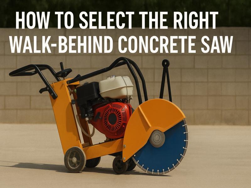
Buyer’s Guide: How to Select the Right Walk-Behind Concrete Saw
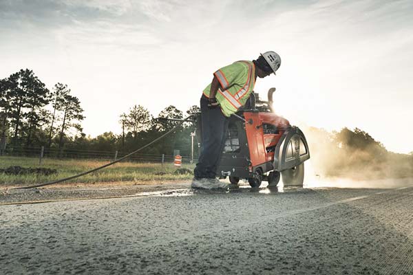
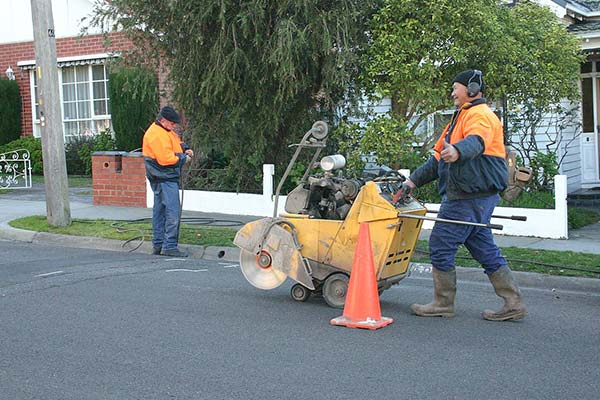
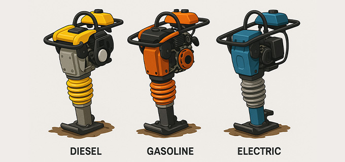
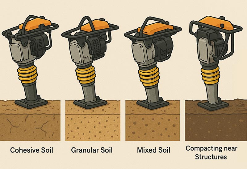
Walk-behind concrete saws are indispensable machines on modern construction sites. Whether you’re cutting expansion joints in highways, removing damaged slabs, or installing underground utilities, the right walk-behind saw can dramatically improve productivity, safety, and cut quality. Purpose of the Walk-Behind Concrete Saw Before diving into specs, first identify your primary application. Walk-behind saws are used for: Sawing through concrete or asphalt surfaces Creating expansion or control joints Trenching for plumbing, electrical, or telecom lines Demolishing and removing damaged surface slabs Performing decorative scoring on flatwork Understanding the material (concrete, asphalt, reinforced concrete), cut depth, location (indoor/outdoor), and frequency of use will guide your equipment selection. Types of Walk-Behind Concrete Saws Walk-behind saws can be classified by power source, cutting method, and intended application. Power Source Options Power Source Best For Key Characteristics Gasoline Outdoor use High torque, portable, loud, emits fumes Diesel Heavy-duty applications Long-lasting, fuel-efficient, louder Electric Indoor use Quiet, emission-free, needs power source Hydraulic Utility or underwater use Compact, safe in hazardous environments Key Features to Evaluate Blade Size and Maximum Cutting Depth Blade diameter limits the concrete saw’s maximum possible cutting depth. Common blade sizes are 14″, 18″, 20″, 24″, and even 36″, providing cut depths from 4 to 14 inches. Blade Size Approx. Cutting Depth 14 inches 4.5 inches 18 inches 6.5 inches 20 inches 7.5 inches 24 inches 9.5 inches 36 inches 14 inches Choose a saw with a blade guard that supports your target blade size and future expansion needs. Motor/Engine Power A powerful engine helps maintain RPMs during deep or continuous cuts. Small jobs: 8–13 HP engines Medium jobs: 13–20 HP engines Heavy-duty jobs: 20+ HP Look for branded engines like Honda, Kohler, or Briggs & Stratton for quality assurance. Consider if you need torque over speed for tough materials like reinforced concrete. Chassis Design and Build Quality The chassis determines the saw’s durability and handling. Prioritize: Heavy-gauge steel frames for vibration resistance Balanced weight distribution for straight cuts Adjustable handlebars for ergonomics Integrated lifting hooks for easy transport Shock-absorbing wheels to reduce vibration and operator fatigue Wet vs. Dry Cutting Capabilities Wet cutting cools the blade with water and minimizes dust for safer, cleaner concrete cutting. Dry cutting is ideal in areas where water isn’t allowed. Choose a saw that supports: Wet cutting only (requires water tank or hose) Dry cutting only (needs dust control system) Dual-mode (most versatile) Important: Wet cutting is typically safer and extends blade life, especially for deep cuts. Blade Guard and Blade Shaft Ensure the blade guard is easy to lift, robust, and corrosion-resistant. Look for: Hinged or sliding guard for quick blade changes Flush cutting guard option for edge cuts Heavy-duty arbor shaft with precision bearings A self-aligning blade shaft improves cut straightness and reduces wear. Depth Adjustment Mechanism Precision matters, especially on slab joints. Your saw should have: Screw-type or hydraulic depth control for accurate cutting Clear depth indicators for repeatable settings Locking mechanism to prevent drift during operation Maneuverability and Weight While heavier saws provide better traction and stability, overly bulky units are harder to transport. Consider: Wheel size (larger wheels for rough terrain) Balance and pushability Turning radius (tight spaces vs. open roads) Overall weight and how it affects cut performance Water Supply and Dust Control Look for saws with: Integrated water tanks (5–20 gallons) Dual water nozzles for both sides of the blade Vacuum ports or shrouds for dry cutting Adjustable water flow control Note: OSHA’s regulations require silica dust suppression for concrete cutting jobs. Ensure the saw is compliant. Safety Features to Look For A professional walk-behind saw should include: Emergency shut-off switch Blade guard with full coverage Vibration-damping system Throttle control near handle Spark arrestor (for gas/diesel engines) Also, check that the unit comes with safety decals, manuals, and maintenance guides. Maintenance and Serviceability Over time, you’ll need to replace blades, belts, and bearings. Choose a saw that’s easy to service: Tool-free blade change access Removable belt covers Grease points for blade shaft bearings Engine accessibility for oil/fuel changes Service parts availability from the manufacturer or dealers Saws with modular parts make maintenance quicker and cheaper. Warranty, Support, and Manufacturer Reputation Never overlook after-sales service. Consider: Warranty duration (at least 12 months for engine and chassis) Availability of spare parts Customer support responsiveness Online documentation, videos, or manuals Local distributor or service center access Reputable manufacturers often offer lifetime support, technical guidance, and operator training resources. Cost vs. Value Considerations Although initial cost matters, consider long-term value: Initial Cost Operating Cost Total Value Budget saws (~$1,000–$3,000) May require frequent maintenance OK for light use Mid-range saws (~$3,000–$6,000) Balanced performance and durability Best for general contractors Premium saws ($6,000+) Low wear, reliable, operator-friendly Ideal for large-scale operations Don’t forget to budget for: Diamond blades (varies by size and material) Water kits, vacuums, spare parts Operator training Real-World Examples Use Case Recommended Saw Features Highway concrete cutting Diesel-powered, 24″ blade, wet system Indoor slab removal Electric motor, dry cutting, HEPA vacuum Decorative scoring Lightweight, precision depth control Bridge deck trenching Gas-powered, 18–20″ blade, flush cutting Questions to Ask Before Purchasing What types of materials will I cut regularly? What’s my average required cut depth? Will the saw be used indoors or outdoors? Do I need OSHA silica dust compliance? How many hours per day will the saw run? Is water and power available at the job site? Can I easily find parts and service near me? These questions will help align your needs with the best equipment configuration. Buy for Performance, Not Just Price A walk-behind concrete saw is a long-term investment in your productivity, safety, and job quality. Cheap machines may save you money upfront, but they often lead to blade wear, inconsistent cuts, frequent breakdowns, and higher lifetime costs. As a manufacturer, we recommend choosing a saw that balances: Engine or motor reliability Blade compatibility and cutting depth Precision and safety features Wet/dry cutting adaptability Low maintenance and service support We offer a full line of walk-behind saws designed