A diesel generator is compatible with an automatic transfer switch only when the control interface, electrical ratings, neutral arrangement and operating sequence work together in the proposed installation. Electric starting or an “ATS-ready” description is not enough. Ask the supplier to identify the proposed generator and controls in a signed-off compatibility record covering the transfer device and every connecting interface. The installer also needs the wiring documents and operating limits to assess the complete system.
The key is to distinguish two jobs. The control system requests and manages generator operation. The transfer equipment changes the load’s power source. A compatible purchase must address both jobs, including what happens when utility power fails, the engine cannot start, the generator output is unsuitable or the normal supply returns.
First, define what the ATS will serve
List the circuits that need backup power and identify their voltage, frequency, phase arrangement and demand. Include starting loads and equipment that cannot tolerate a supply interruption. Decide whether the generator will serve a limited essential-load board or a broader installation. This determines the electrical capacity and operating sequence that the supplier and installer must review.
Describe the normal supply as well. Select the ATS against the source characteristics and the loads it will switch, including its pole configuration and applicable ratings. A generator outlet rating does not establish the rating of an entire building supply connection. The qualified installer should assess the complete installation, including protection and applicable local requirements, before the equipment selection is finalized.
An ATS does not normally eliminate the interruption while a generator starts and becomes ready. If equipment needs continuity through that interval, identify it explicitly. The installer may need a separately designed solution to support those loads. Do not describe an ordinary generator-and-ATS combination as an uninterruptible power supply without evidence for the complete arrangement.
Checkpoint 1: identify the exact generator build
Record the model, engine, alternator, controller and selected output configuration. Match the quoted output rating to the required supply voltage, operating frequency and number of phases. If the manufacturer offers several panels under one model family, identify which panel is included. Ask whether ATS-related equipment is fitted, supplied separately, available as an option or absent from the base quotation.
The Excalibur diesel generator range lists ATS options, but an option list is only the beginning of compatibility review. Ask for the approved pairing for the actual order. Include any required harness, connector, charger, controller upgrade or additional component in the commercial scope so the equipment can be commissioned as intended.
Evidence to request
Obtain a configuration sheet, control-panel photograph and wiring document bearing consistent model or revision references. Ask the supplier to resolve any differences between them. A photograph showing a socket labelled ATS does not establish the signal requirements, pin assignments or compatible accessory. Use the documents issued for the supplied generator revision to establish these interface details.
For repeat orders, ask whether an earlier approved ATS remains compatible with the current generator revision. A similar connector or unchanged model name does not prove that controller behavior and wiring remain identical. Treat a change of controller or harness as a reason to review the pairing before shipment.
Checkpoint 2: match the start and stop interface
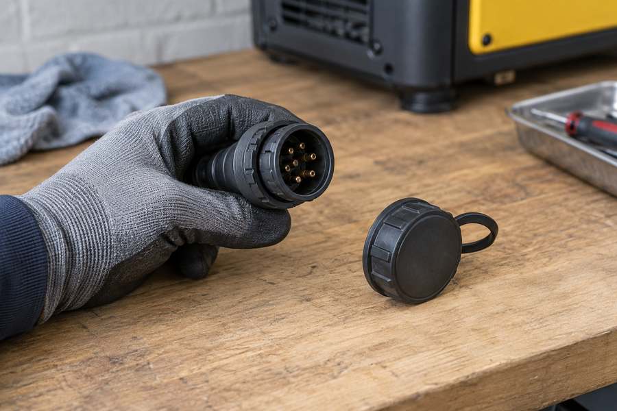
Ask what signal the generator expects and what signal the ATS or its controller provides. The interface may involve an approved contact arrangement, a dedicated connector or another documented control system. Specify the command type and its behavior. A maintained request, a momentary command and a communications message are not interchangeable merely because they can all initiate starting.
Request connector identification and a proper wiring diagram. Confirm control-supply requirements, signal isolation where applicable and the permitted cable arrangement. Never apply a guessed voltage to an unidentified pin. Matching plug shapes confirm only mechanical fit; the pin functions and signal requirements still need checking.
Confirm who supplies each cable and connector
The quotation should state whether the interconnecting cable is included, its approved length or limits, and which terminations are factory completed. If an installer must provide part of the connection, identify the specification and the party responsible for checking it. A missing cable can delay commissioning; an incorrectly specified one can cause a much more serious problem.
Ask how the start request is removed and how the generator responds. The shutdown process may include unloading and a manufacturer-defined cool-down period. Make sure the control interface supports that sequence rather than simply cutting engine power whenever the normal source reappears.
Checkpoint 3: verify power connections and switching ratings
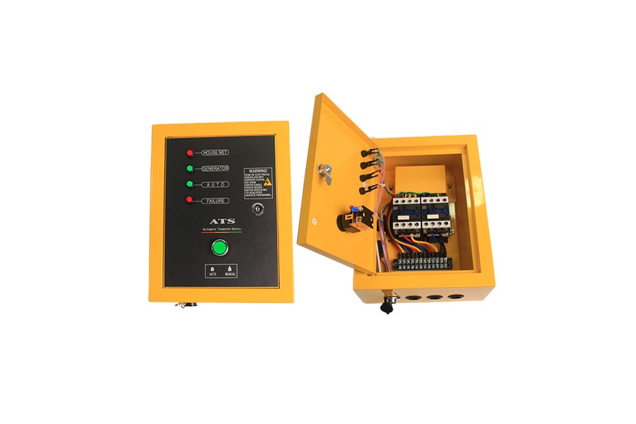
The ATS must be suitable for the supply voltage, frequency, current, phase arrangement and application. Ask the installer to check the load characteristics and the appropriate switching and fault-related ratings. The stated current rating needs supporting switching and application information before the buyer can assess compatibility. The rating and protective arrangement need to be assessed together in the actual installation.
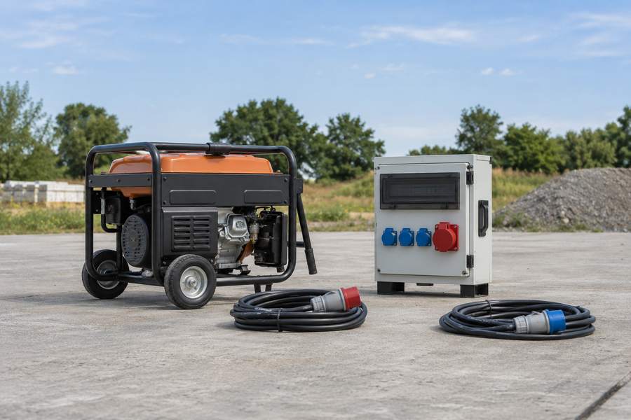
Identify how generator power reaches the transfer equipment. A portable receptacle, terminal connection and inlet arrangement have different practical requirements. Confirm the connection rating and the protection along that route. The generator’s total output may exceed what one supplied socket can carry, so the cable and connection plan must be checked against the intended load.
Neutral and earthing need an installation decision
Ask the qualified designer or installer to determine the neutral switching and earthing arrangement for the proposed sources. This affects the required transfer equipment and protective devices. Do not assume that a three-pole or four-pole product is correct solely because the generator is three-phase. The installation design, source configuration and applicable requirements determine the appropriate arrangement.
The supplier should provide the generator’s neutral and grounding information clearly enough for that review. Where an RCD or other residual-current protection is required, its interaction with the system must be assessed. Avoid treating an earthing terminal or a product brochure’s general protection claim as a substitute for installation-specific design.
Checkpoint 4: agree on the operating sequence
Write the intended sequence in plain language before discussing timer settings. What condition initiates a start? How does the system confirm acceptable generator output? When is the load transferred? What happens if the engine starts but the voltage or frequency is unacceptable? The answers should describe behavior that can be demonstrated during commissioning.
Include the return to normal supply. Specify the conditions for retransfer, the treatment of a brief utility return, the unloading sequence and the final generator stop. These functions should follow the approved controller and engine requirements. Avoid imposing a convenient timer value without checking whether it produces suitable operation for the application.
| System event | Required confirmation | Acceptance evidence |
| Normal supply fails | Detection and start request behavior | Controlled mains-failure simulation |
| Engine starts | Output acceptance before load connection | Recorded sequence and measurements |
| Engine fails to start | Alarm, lockout and user indication | Approved failed-start simulation |
| Generator output becomes unsuitable | Load and engine response | Approved functional test |
| Normal supply returns | Retransfer and shutdown sequence | Timed commissioning record |
| Maintenance is required | Prevention of automatic starting | Documented isolation procedure |
The purpose of this schedule is to expose missing decisions. Fill in the actual acceptance criteria with the supplier and installer. It is not a universal set of control settings, and it should not be used to modify an unfamiliar controller without the manufacturer’s instructions.
Checkpoint 5: review readiness during standby
An automatic system depends on the generator being able to start when requested. Ask how the starting battery will remain ready during standby and which charging equipment is included. Confirm the approved storage and maintenance arrangements, including fuel condition and any temperature-related starting preparation. Automatic control does not remove the need for scheduled inspection.
Ask what monitoring is available while the engine is stopped. The system may provide indications for battery condition, a disabled operating mode or other readiness issues, but these functions must be confirmed for the supplied equipment. A control panel that displays engine data only while running may not provide the standby information the operator expects.
Assign responsibility for routine checks
Identify who will check the machine, respond to alarms and organize periodic tests. The documents should explain the required checks and how to record them. If the installation is remote, specify how a fault reaches the responsible person. An automatic start function without an agreed response process can leave a failed system unnoticed until power is needed.
Discuss how planned testing affects connected equipment. A test that starts the engine without transferring load demonstrates different things from a test of the complete transfer sequence. Both can have a role, but their purpose and limitations should be understood. Follow the supplier’s and installer’s approved procedure for the site.
Checkpoint 6: confirm the generator is suitable for the location
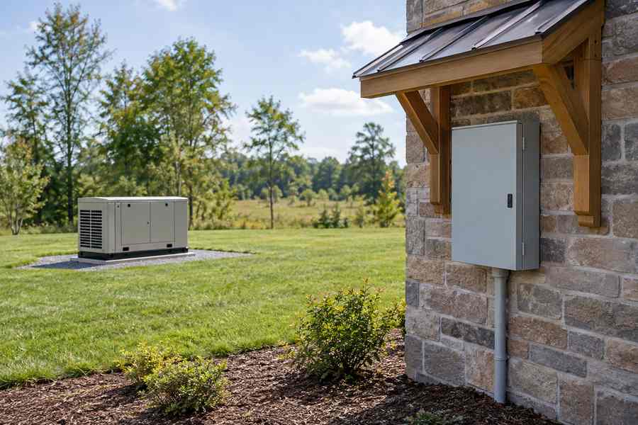
Some buyers focus on the ATS while leaving the generator’s operating location unresolved. Reverse that sequence: establish the site conditions and operating duty first, then assess the proposed generator against them. Portable generators require an appropriate outdoor operating location with exhaust kept away from occupied spaces and openings, following the manufacturer’s instructions. Automatic starting makes it especially important that the location remains suitable without someone standing beside the machine.
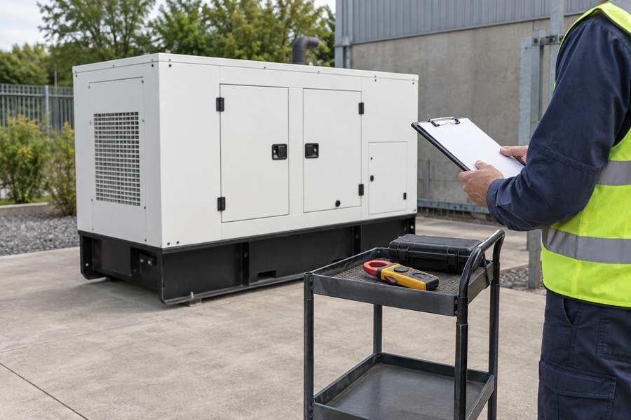
An enclosed product from the silent diesel generator range still needs its specified airflow, exhaust and service clearances. A sound-reducing housing is not permission to install the machine indoors or in an unapproved compartment. Confirm weather exposure, physical protection and access with the manufacturer and installer.
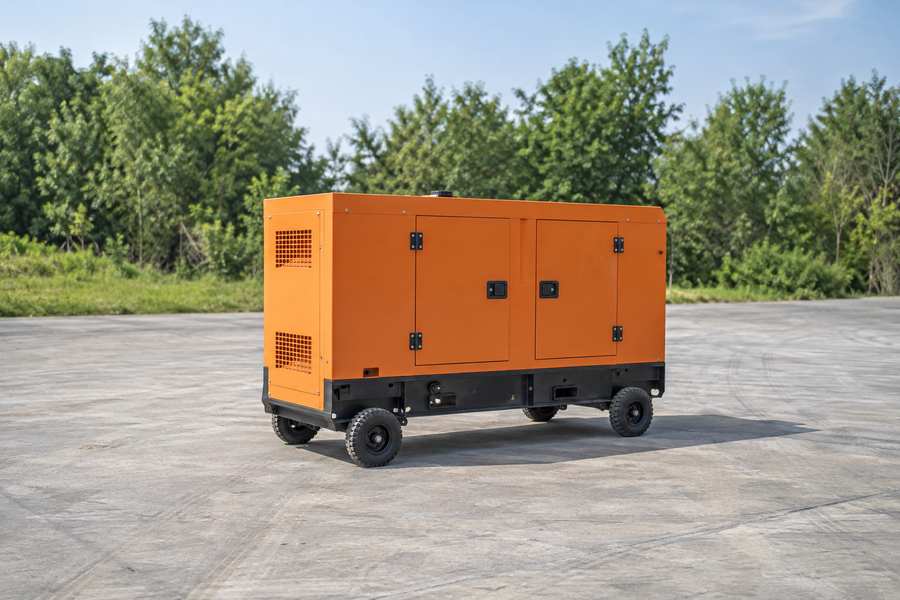
If an open diesel generator is proposed, check the environmental and installation restrictions for that exact model. Any shelter or protective arrangement must preserve the required cooling and exhaust conditions. Do not assume a locally improvised enclosure will be acceptable simply because it keeps rain off the panel.
Checkpoint 7: obtain a complete commissioning package
The delivery should include the approved wiring diagrams, interface information, operating sequence and relevant settings record. It should identify the generator and ATS versions, supplied cables, protective devices and responsibilities for site work. Separate the checks already recorded at the factory from the tests assigned to the installation and commissioning team. Those are complementary stages, not substitutes for each other.
Commissioning should demonstrate the real system with suitable controls and precautions. Include normal operation, the start-and-transfer sequence, return to normal supply and approved simulations of relevant failures. Record the measurements and observed responses. Do not create damaging engine conditions or unsafe electrical faults merely to test a protection feature; use the manufacturer’s accepted methods.
Include operator handover
The person responsible for the installation needs to know the operating modes, alarm indications, isolation procedure and steps for obtaining service. Explain which actions are routine operator tasks and which require qualified personnel. Provide the documents in a language the responsible team can use, and ensure they match the delivered panel and controller revision.
For distributors, include this requirement in the order even if the final installation is handled by another company. Clear technical documents make it easier to assess compatibility before the generator reaches the end customer. They also reduce the temptation to improvise wiring when the supplied equipment does not behave as expected.
A useful pre-order decision
Approve the pairing when the supplier and installer can connect four pieces of evidence: the exact generator configuration, the documented start interface, suitable transfer equipment and an agreed operating sequence. Keep unresolved items visible. A note saying “ATS optional” should not be converted into a confirmed automatic-backup specification until those items are addressed.
Keep a record of the approved cable routing and accessible termination points as part of the installation handover. If the generator must be disconnected for transport or service, ask how the system will be made safe and how it will be checked after reconnection. A portable unit may be removed more often than a permanently installed set, so the reconnection process deserves explicit attention. Provide connector identification and repeatable test instructions that remain usable when a different technician takes responsibility for the installation.
The final purchase description should name the included equipment and its boundaries. State what is factory fitted, what arrives separately and what is commissioned on site. That turns ATS compatibility from a marketing label into a deliverable that can be inspected, tested and handed over with confidence.