Top 5 Features to Look for in a Pencil Concrete Vibrator
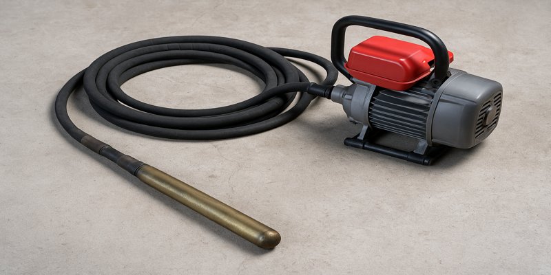
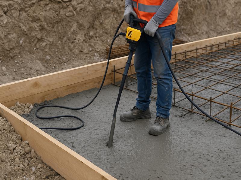
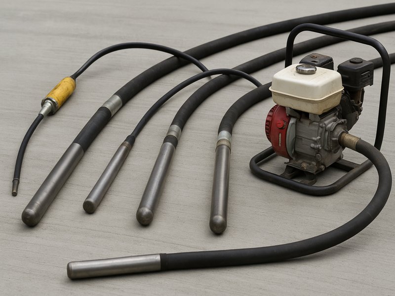
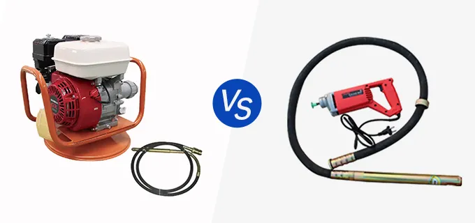
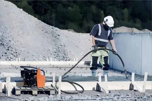
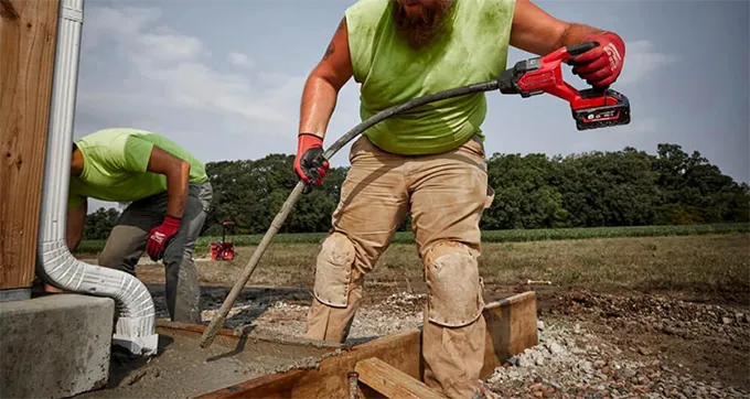
When it comes to achieving solid, void-free concrete pours, the pencil (or “poke”) vibrator is a vital tool in your arsenal. Compact yet powerful, it efficiently removes air bubbles (aka “honeycombing”), ensuring structural integrity. But not all pencil vibrators are created equal. To get the best results—and maximum durability—look for these five key features: Motor Power & Vibration Frequency (VPM/RPM) Why it matters: A more powerful motor paired with high vibration frequency ensures deeper and faster consolidation of concrete. It’s particularly crucial for high-density mixes or low-slump concrete. Modern models achieve around 12,500 vibrations per minute (VPM); some go even higher, up to 14,000 VPM. For instance, Milwaukee’s M18 FUEL Pencil Vibrator delivers 1.8 peak horsepower and 12,500 VPM, outperforming many rivals. Tips: Prioritize vibrators offering 10,000+ VPM for consistent and deep consolidation. A variable-speed trigger can be invaluable—allows fine-tuning while working around rebar or formwork. Portability & Power Source: Cordless vs. Corded vs. Gas Why it matters: Your jobsite conditions often dictate the best power source: Cordless (battery-powered): Great mobility and reduced trip hazards—no tangled cords. Milwaukee’s cordless pencil vibrator clears up to 20 yd³ per charge using its REDLITHIUM XC6.0 battery. Corded (electric): Unlimited run time and typically lighter tools, but restricted by cord reach and availability of outlets. Gas-powered: Ideal for remote or infrastructure-heavy jobsites with no reliable electrification; however, these tend to be heavier, noisier, and emit fumes. Tips: For most urban or site-specific work, cordless with a robust battery system (like Milwaukee’s M18) offers freedom and efficiency. If you often work far from power and noise/economy isn’t a concern, gas models remain a viable option. Head Design & Whip/Shaft Quality Why it matters: Head shape and diameter determine vibration amplitude and penetration. Some heads (like square designs) provide stronger amplitude than round ones . Whip/shaft durability is equally crucial—thin or poorly made whips can burn up fast under high vibration and heat. Details to check: Head: 1″ diameter is common; opt for square or thicker heads for tougher mixes. Whip: Look for heavy-duty, heat-resistant casing; lengths vary—4 ft, 8 ft, or longer depending on your project’s depth. Motor Protection & Smart Electronics Why it matters: Concrete environments are tough—wet, abrasive, and intermittent use can stress your tool’s motor. Milwaukee equips its M18 FUEL lineup with REDLINK PLUS intelligence and overload protection, enabling communication between battery and tool for optimized performance and safety. Additional protection features may include: Thermal overload cutoff Sealed or reinforced housing Heat dissipation vents or cooling systems What to look for: A tool that can endure heavy use Electronic safeguards to prevent motor damage Brands offering these protections typically have longer tool lifespan Ergonomics, Weight, and Ease of Use Why it matters: Vibration and heavy tools can quickly exhaust operators—especially with extended use. Weight difference: Milwaukee’s 4 ft model weighs about 8.8 lb, whereas the 8 ft version is 14.3 lb—choose according to job length and operator stamina. Trigger control: A variable-speed trigger adds actionable finesse when working near reinforcing bars or edges. Handle comfort: An ergonomic grip reduces fatigue and improves precision during long sessions. User feedback: Contractors often report battery drain on high-output tools. As one Reddit user mentioned, ‘It drains the batteries quickly.’ Using high-capacity battery packs (like 6.0 Ah vs 3.0 Ah) substantially extends runtime. Bringing It All Together: Feature Comparison Table Feature What to Look For Why It Matters Power & Vibration Frequency ≥ 10,000 VPM, high HP Deep consolidation and stronger performance Power Source & Portability Cordless w/ high-capacity battery, or corded/gas based on jobsite needs Mobility or extended runtime, depending on context Head & Whip Quality Square or durable head; heavy-duty whip with appropriate length Effective reach and long-term durability Motor Protection Electronics/overload safeguard (e.g., REDLINK PLUS) Longevity and reliability in tough conditions Weight & Ergonomics Balanced weight, comfortable handle, variable-speed trigger Operator comfort, control, and reduced fatigue Practical Example: Milwaukee M18 FUEL Pencil Vibrators 4-ft model (2910-20): – 1.8 HP, 12,500 VPM, 8.8 lb, variable-speed trigger, smart protection, cordless. 8-ft model (2911-20): – Same performance specs, but longer reach (8 ft) and weight increases to 14.3 lb. Both models offer cordless operation, smart electronics, and robust consolidation—making them excellent case studies in feature-rich equipment. Usage Tips to Maximize Those Features Insert & Withdraw Properly: Insert vertically before turning on; withdraw at ~1 in/sec, stopping when no more bubbles appear. Overlap Zones: Each insertion should overlap by about four times the head diameter to ensure full consolidation. Use Appropriate Battery Capacity: Larger batteries (6 Ah+) significantly extend duty time on high-output tools . Rotate Tools & Whips: To even wear and extend service life. Watch for Heat: Motor-protected models help—but allow cooling between uses if operating in high-heat environments. Selecting the right pencil concrete vibrator involves more than just choosing a high-powered tool. It’s about finding the balance between performance, mobility, durability, and operator comfort. Prioritize models offering: High motor power & vibration rate A flexible, job-matched power source Durable head and shaft design Smart motor protection Ergonomic and manageable weight Armed with these criteria, you’ll nail void-free, structurally sound concrete every time.